Home > High Frequency PCB
High Frequency/high speed PCBs are mostly used in the applications which involve special signal transmissions. They mostly operate in higher electromagnetic frequency range from 300 MHz(wavelength less than 1 meter) to 3 GHz(wavelength less than 0.1 meter). Nowadays a lot of the electronic products involved in signal communication. This is more prominent in products that related to satellite and Wi-Fi systems. High speed high frequency communication equipment is the development trend, especially 5G networks, the increasing development of satellite communications, electronic products are moving towards large capacity, and low latency.
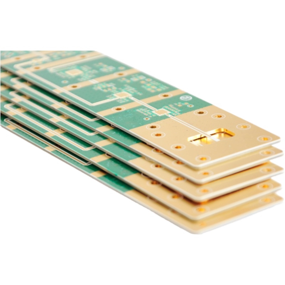
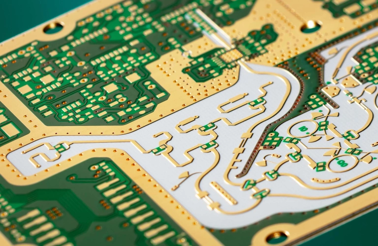
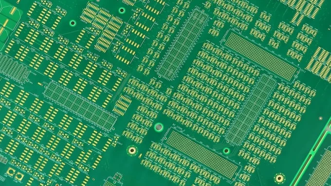
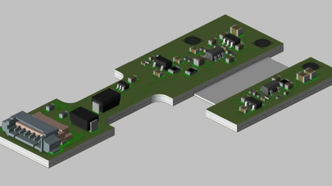
High frequency printed circuit boards (PCBs) are specialized circuit boards engineered to operate efficiently at frequencies typically above 1 GHz. They are critical in applications such as telecommunications, radar, RF and microwave systems, and high-speed digital devices. The design, materials, and fabrication of high frequency PCBs are optimized to minimize signal loss, maintain signal integrity, and ensure reliable performance at elevated frequencies.
Materials used for high frequency PCBs have a low dissipation factor, which reduces signal loss during transmission.
Ensures consistent signal speed and minimizes signal distortion across different frequencies.
Essential for high-speed signal transmission, with precise trace width and spacing calculations.
Helps maintain signal fidelity by reducing resistance at high frequencies.
Common materials include PTFE (Teflon), Rogers, and other hydrocarbon ceramic laminates, instead of standard FR4.
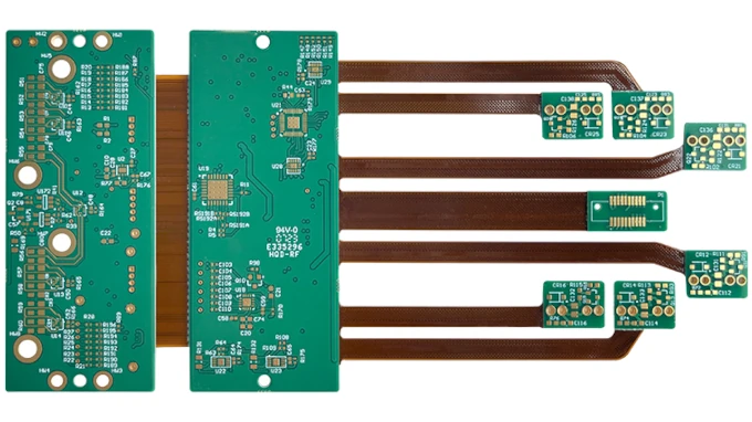
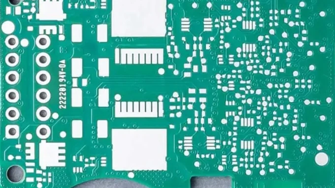
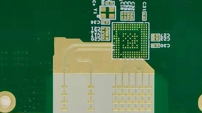
The correct choice of materials and precise PCB manufacturing techniques are vital to ensuring reliable, high-speed, and low-loss performance for high frequency applications. As electronic devices demand faster data rates and work at higher frequencies, high frequency PCBs are becoming increasingly important in modern technology.
A high-frequency PCB is designed for circuits operating above 500 MHz, often used in RF, microwave, and high-speed digital applications. They require specialized laminates and precise fabrication to maintain signal integrity.
Common materials include Rogers, Taconic, Isola, and Nelco laminates. These have stable dielectric constants (Dk), low dissipation factors (Df), and controlled thermal expansion, which reduce signal loss at high frequencies.
Controlled impedance ensures consistent signal propagation without reflections or distortion. At gigahertz frequencies, even small variations in trace width, dielectric thickness, or material Dk can degrade performance.
Unlike FR4-based PCBs, high-frequency boards use low-loss materials, tighter manufacturing tolerances, smoother copper foils, and more precise stack-up design to maintain high signal integrity.
Challenges include managing dielectric thickness, controlling copper surface roughness, ensuring precise etching, and preventing resin flow during lamination that could alter impedance.
Specialized tools like TDR (Time-Domain Reflectometry) and VNA (Vector Network Analyzer) measure impedance, insertion loss, and return loss. Cross-sections and AOI are also used for structural quality checks.
Yes, because advanced laminates cost more, fabrication requires high-precision equipment, and yield rates can be lower due to strict tolerance requirements.
Applications include 5G base stations, radar systems, satellite communications, aerospace and defense, automotive ADAS systems, and high-speed networking hardware.
ENIG (Electroless Nickel Immersion Gold), ENEPIG, or immersion silver are commonly used because they maintain smooth surface profiles and stable impedance. HASL is generally avoided due to uneven surface finish.
IPC-6018 (for RF/microwave PCBs), IPC-2221 (generic design standards), and IPC-6012 (qualification and performance) are commonly followed to ensure reliability and consistency.
Common FAQ topics. If you have specific questions in mind, feel free to ask!