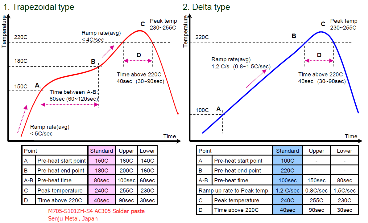
Reflow soldering temperature setting is a precise and critical process in electronics manufacturing, as it determines the quality and reliability of solder joints by carefully controlling the heating and cooling of circuit boards during assembly. Proper temperature profiling ensures effective solder flow, minimizes thermal stress on components, and leads to robust connections, all of which are crucial for the long-term performance and durability of electronic devices.
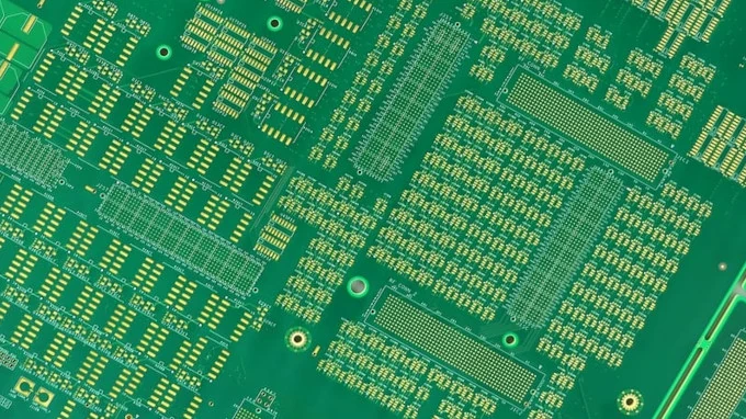
HDI PCB Key Features High-Density Interconnect (HDI) PCBs are advanced circuit boards designed for complex, high-density electronic assemblies. The key